How to wire 3 phase induction motor?
Wiring a three-phase induction motor involves connecting three power wires and three control wires to the motor terminals. The control wires are typically connected to a motor starter or contactor that controls the motor's speed and direction of rotation.
Wiring a three-phase induction motor is not a particularly difficult task, but it is important to follow the proper steps to ensure that the motor is wired correctly. The following steps outline the process of wiring a three-phase induction motor:
-
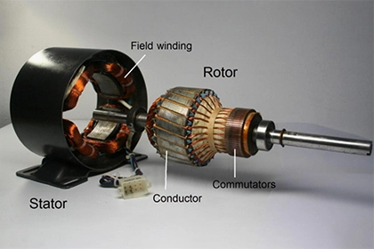
Identify the terminals on the motor: The first step in wiring a three-phase induction motor is to identify the terminals on the motor. Most three-phase induction motors will have six terminals, labeled U, V, W, X, Y, and Z. The U, V, and W terminals are the stator windings, and the X, Y, and Z terminals are the rotor windings.
-
Connect the power supply: The next step in wiring a three-phase induction motor is to connect the power supply to the motor. The power supply for a three-phase induction motor should be a three-phase AC voltage, typically in the range of 208-240 VAC. The power supply should be connected to the U, V, and W terminals on the motor.
-
Connect the control circuit: The control circuit for a three-phase induction motor is used to start and stop the motor, and to control its speed and direction. The control circuit should be connected to the X, Y, and Z terminals on the motor.
-
Install a protective device: A protective device, such as a fuse or circuit breaker, should be installed in the power supply circuit to protect the motor from damage in case of an overload or short circuit.
-
Test the motor: Once the motor has been wired, it should be tested to ensure that it is operating correctly. The motor should be started and run at various speeds to verify that it is functioning properly.
In summary, wiring a three-phase induction motor involves identifying the terminals on the motor, connecting the power supply, connecting the control circuit, installing a protective device, and testing the motor to ensure that it is operating correctly. By following these steps, a three-phase induction motor can be wired safely and efficiently.


Leave a Comment